Chief Engineer's log..
Stardate -303524.4823059361For some time i wanted to modify my Craftbot Plus to the V6 hotend ecosystem as it offers more possibilities and part availability for future projects and general maintenance. This is a quick write-up of the modifications i performed:
Required Items:
BOM:- 1x V6 Heat sink
- 1x V6 Heatbreak
- 1x V6 Heater Block
- 1x V6 Heater Cartridge (24V, 40W, optional)
- 1x V6 Thermistor Cartridge (100kOhm NTC, optional)
- 1x MK8 heatbreak (40 mm long)
- 1x Saw
- 1x File
- M6 Thread Tap
- 5 mm Drill
or alternatively a mill with appropriate endmills and a lathe.
Modifying V6 Heat-Sink
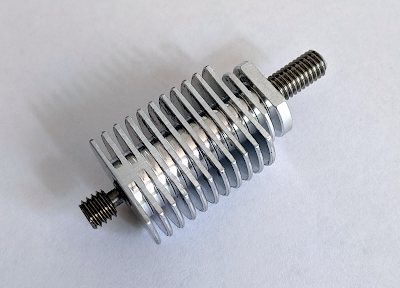
The standard V6 hotend cannot be directly mounted to the Craftbot Plus and has to be modified prior to be mounted. First the heat sink has to be milled flat on one side (Alternatively this can also be accomplished using a file). The new width of the heat sink should be about 18.5 mm but no more than 19 mm, otherwise it will not fit under the extruder mount.
The second modification is to remove the upper part of the groove mount. Leave the lower side of the mount as this ensures the correct length of the heat sink. I used a lathe to do this but a saw and a file should do as well, just make sure to work slow and the top of the heat sink is perpendicular to the sides. The heat sink should now have a length of about 33 mm and look something like this:

the last modification required to the heat sink is to drill out the center width a 5 mm drill and tap it with a M6 screw tap all the way through. When this is done all that is left is to clean up all the edges and remove any leftover metal chips from the modification. Lastly clean the M6 thread with rubbing alcohol to remove any leftover oils or fats
Assembly
First screw in the new V6 heat break as far as you want it to (align the M6 thread with the lower end of the heat sink). Then apply a bit of loctite to the one end of the mk8 heat-break and screw it in as far as it goes until it hits the V6 heat-break. tighten it down (only finger tight) and let it cure. When cured, cut the M6 thread to length so it ends just before it is touching the drive gear or the idler (about 13 mm of the M6 tube should stick out the heat sink)

Once the heat sink is assembled it can be mounted in the Craftbot Plus using the same method used for mounting the original hotend. The only thing left to do now is replace the thermistor with a cartridge type if the newer version of the heater block is used (for the older type, the original thermistor can be used) and the printer is ready to print again.

Modifying the Starting gcode in your Slicer
The firmware has peculiar function that regulates the extruder fan as a function of the set temperature. Unfortunately the default setting that is used uses a to low setting to properly cool the V6 heat sink. If nothing is done heat creep will occur and clog the nozzle. Luckily there is a way to modify the parameters used to calculate the fan speed using the M1006 gcode as reported here: https://www.craftbot.nl/. Setting the variable H to 350 works quite well for me. Hence i added the following line to my starting gcode:
M1006 S2 H350 ; spin the extruder fan faster
Happy Printing!